Self-study lesson plans and training record download page.
Hydraulic Circuits Design Symbols
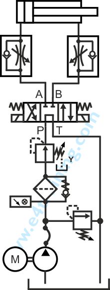
Hydraulic symbols can provide a clear representation of the function of each hydraulic component and therefore laying each symbol out on the page in the same way the components are placed in the circuit allows for the complete function of the hydraulic equipment to be diagnosed and understood.
Hydraulic Symbols Explained
Go to our hydraulic symbol training module for a full explaination or what they represent.
- Basic symbol introduction
- Check or shut off valves
- Directional control valve symbols
- Pressure control valve symbols
- Hydraulic flow control valve symbols
- Servo and proportional valve symbols
- Slip-in logic cartridge valve symbols
- Hydraulic pump symbols
- Ancillary hydraulic equipment symbols
- Hydraulic measuring equipment symbols
- Hydraulic actuator symbols
- Valve actuation mechanism symbols
- Hydraulic course lesson plans
Hydraulic symbol standards
It would be nice to think that each type of valve had its own symbol and that all valves can be clearly defined, however, the international standard has been the focus of much discussion for many years and is something of a compromise. The problem is that manufacturers often have subtle differences in the detail of their valve design which they'd all like to form part of the standard symbol.
A relief valve, for example, may always have the same basic function but can be constructed in significantly different ways. Cost may vary between £10 and £1000 and performance may be equally different. As a hydraulics engineer, it's important to understand the difference but this may not always be possible from the symbol. For example, knowing whether the valve uses a sealed poppet, spool element or both can make a big difference to the circuit operation; as can pilot feed or orifice positions etc.
Advanced circuit design techniques
The approach we recommend is generally to build your own larger symbols from the same basic elements whenever more detail is required. If you learn the basics you should be able to interpret all circuits provided you pay particular attention whenever the fine detail changes. Sometimes putting too much detail will confuse things, so designers leave it out. Often the manufacturers are not keen to disclose too much information on what is essentially their own unique IP that has probably taken them many years to develop.
Caution when analysing a circuit
Always be careful not to assume circuit drawings are correct. Circuits may be changed without the drawings being updated and some are just plain wrong. Use them as a master to work through the components in the actual circuit you are working on; checking the valves to the symbols as you go.