What is hydraulic noise

Fluid power systems can be noisy. They often transmit large installed powers via the hydraulic fluid and even small discontinuities in this power transmission can create loud mechanical noises.
In simple terms:
1. Noise sources
Fluid flow is not completely smooth but oscillates due to the movement of the pistons, vanes or gears in hydraulic pumps. For example, a pump with 9 pistons or gear teeth rotating at 1000 rev/min may produce an average flow of 20 L/min but the actual flow might be alternating between a maximum of 20.2 and a minimum of 19.8 L/min with a fundamental frequency of 150 Hz.
Noise and heat may also be generated in areas where high pressure drops or flow rates occur across control valves or where valves switch instantly rather than with a smooth transition from open to shut. Cavitation, or more commonly air bubbles being drawn out of solution before collapsing, can create an audible noise and exhibit a particularly high noise frequency.
Valve instability is another potential source of hydraulic noise. This is when valves no longer operate smoothly but oscillate in an unstable manner, often at high frequencies and with hasrh mechanical contact of metal poppets against their metal seats.
2. Noise transmission
The flow discontinues interact with the circuit impedance to create local pressure ripples. P=QZ (Pressure = Flow * Impedance) applies to hydraulics in the same way as the formula V=IR (Voltage = Current * Resistance) applies to electrical circuits. Both are not simply, one-dimensional equations but are mathematically complex e.g. cover a full range of frequencies. In simple terms this means that while our hydraulic pump may have a natural frequency based on its 9 pistons, the circuit will also exhibit higher harmonics of this frequency e.g. 9*N, 18*N, 27*N etc. where N is the pump speed.
3. Noise radiation
The pressure ripple at any point within a circuit may have sufficient energy to excite the body, mounting or framework of a component within the hydraulic system. Unacceptable noises often occur when the pressure ripple creates a standing wave within the system or its frequency matches the natural frequency of the component, mounting or panel, at that point in the circuit. Another factor that affects how offensive the noise might be is its frequency. For example a 9 tooth gear pump is likely to create a much larger pressure ripple than a 12 tooth gear pump providing the same flow rate. However, the lower noise level generated by the 12 tooth pump will be at a higher frequency and potentially could be more offensive to the human ear.
How to measure hydraulic noise
Measuring air-borne noise
If you have a concern about a machine's noise level then you've probably been measuring the airborne noise level in dBA at typically 1 meter from the machine. This of course is what matters as a priority for protecting the health and safety of your employees but it can be of little help in diagnosing and reducing the level of noise. To find more information on measuring air-borne noise there are many great resources online but we do not cover it in detail here.
When you try to research potential solutions for reducing noise it's likely the only information you will find are the airborne noise measurements for different pumps, recorded in the manufacturer's anechoic chamber. These may well be the best information available but are still of limited use for predicting the final system noise level. They do represent the sum of the source flow ripple and pump body radiation, but little else.
Measuring flow ripple and blocked acoustic pressure
Ideally we'd like to measure a pump's flow ripple as this is likely to be the original source of most of the noise. Even better is to know a pump's ‘blocked acoustic pressure'. This is a directly comparable figure that defines what a pump's pressure ripple will look like across the first 10 harmonics. The procedure for measuring these was developed at Bath University in the early 1980s but the International Standard (see ISO 10767) has not been widely adopted across the industry. However, understanding what this measures and how the results will vary between pumps and systems is very helpful when trying to diagnose and solve noise issues. So here is a quick summary of how it works and what it measures. A small circuit is used with a known 'noisy pump', our test pump and a short pipe with lots of pressure transducers in it. Running both pumps together enables some clever software to calculate exactly what flow ripple and blocked acoustic pressure the test pump is producing. Simple really.
The flow ripple result should be relatively simple to understand. It is exactly what flow the pump generates during one revolution e.g. not a constant flow but one that changes as each piston (or gear, vane) oscillates forwards and backwards. Visualising this is useful for pump designers and would be great for comparing different pumps if it was available in manufacturer catalogues, which it isn't.
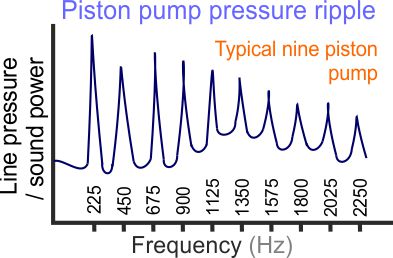
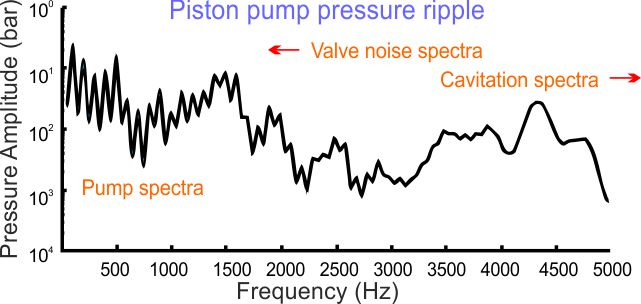
The blocked acoustic pressure is a measure of a standard pressure ripple signature across the first 10 harmonic frequencies. This would be even better for comparing different pumps if it was available but understanding what it tells us is also useful when identifying and diagnosing issues in our system. Looking at the sample graph provided for a typical piston pump we can see that the first and highest pressure ripple is at the pump's harmonic frequency e.g. based on the number of pistons. However, the graph also indicates the pressure peaks for the higher harmonics and these may also be important in our machine. This is because when we measure the machine's air-borne noise we can run a frequency analysis of this reading to see which frequencies are potentially causing the dangerous noise. As we know the dBA recording includes a weighting system to normalise the different noise frequencies in a similar way to how the human ear hears them.
When measuring pressure ripple or air-borne noise signals it is always worth recording a full frequency spectrum to identify and access the important harmonic frequency. More later..
What causes the fluid-borne noise?
Pump fluid-borne noise generators
The flow from a hydraulic pump is never completely smooth. Every pump consists of a discrete number of pumping elements e.g. pistons, gear teeth or vanes. As the pump rotates it produces an average flow rate but this always oscillates up and down around this mean flow. These flow pulsations are based on the number of pumping elements e.g. a pump with 9 gear teeth will exhibit a flow ripple with a frequency of nine times every rotation.
A piston pump might have nine pistons that oscillate forwards and backwards, one after another. The frequency of the flow oscillations will be identical to a nine toothed gear pump rotating at the same speed but the shape and amplitude of the flow ripple will be completely different. A vane pump will also exhibit a completely different ripple shape and amplitude based on the different way its vanes pump the fluid and connect between the inlet and supply side of the circuit. 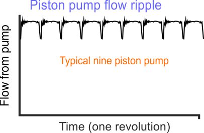
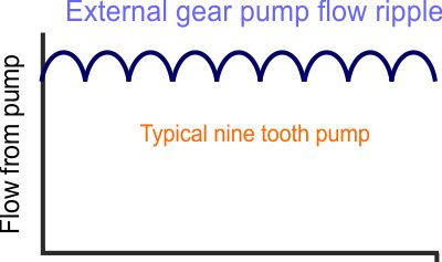
In external gear pumps the shape of flow ripple is defined by gear form and therefore the way the gears mesh together. As the gear teeth close the area trapped between the teeth gets smaller and this area change defines how the flow is exhausted into the circuit and therefore creates the flow ripple curve (shown in our diagram). Increasing the number of gear teeth will significantly reduce the amplitude of the flow ripple while also increasing the frequency of pulsations during one complete rotation. Other factors that can affect the flow pulsations are the quality of manufacturing in areas such as the bridge size between the meshing gear teeth and the gear surface form.
In piston pumps the flow ripple is defined by the number of pistons. The more piston the lower the flow ripple amplitude but the higher the harmonic frequency. The timing plate that controls when the pistons connect with the inlet and supply lines is also important. Open too early and flow may shoot back into the piston or too late and piston pressures will exceed the line pressure. With pumps operating at different speeds, temperatures and fluids etc. it is impossible to have one design that suits all machines so pump manufactures' generally apply different timing plate options for different situations. Another concern with timing plate design is that any flow discontinuities created will generally affect the higher harmonic frequencies which can be more annoying to the human ear.
Vane pumps have all of the same issues as piston pumps although they tend to have more vanes and therefore a lower overall flow ripple.
Internal gear pumps perform in a similar way to external gear pumps but again they have lots more teeth and therefore produce a much lower flow ripple. Of course, the additional sliding face area will create additional leakage and friction.
Hydraulic motors will also exhibit flow discontinuities like their equivalent pump designs. These can also create pressure ripples in the supply and return lines that have the potential to create unwanted airborne noise.
Cavitation, fluid-borne noise generation
Cavitation/aeration is when hydraulic fluid sees exceedingly low pressures caused by very high flows across small restrictions. This causes the fluid to vaporise, which, when the fluid returns to normal pressure, collapses to create very high local pressures, causing an audible, high-frequency noise and often damaging materials close to the impact. In reality, this is more commonly caused by aeration e.g. air being drawn out of solution, rather than cavitation, where the fluid vaporises, but the results are similar. 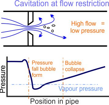
Valve instability, fluid-borne noise generation
Occasionally valves can become unstable and oscillate wildly out of control. This instability is likely to create additional noise as mechanical surfaces hit each other or flow ripples are transmitted to other parts of the circuit. There are many potential causes of instability including:
Air pockets may be present inside the valves, pipework or pilot lines. This can happen from maintenance work, damaged seals or fittings that allow the air to enter the circuit, or faulty 'vent to atmosphere' vent points. Wear on moving parts or operating the equipment outside of its normal working range might also cause instability.
If it's a new system design then there are a range of additional issues that might cause instability. Potentially: interactions with other components, long pipe lengths reducing the system stiffness, direct acting valves instead of pilot operated versions, flow instabilities in poppet or ball valves and closed loop control settings.
Valve switching
Directional valves generally switch from shut to open almost instantaneously. This can cause a harsh noise or judder as the cylinder tries to respond. We will not discuss this much here as it's fairly easy to diagnose and solve by damping the valve movement and using a proportional spool.
How to reduce the fluid-borne noise source
Reducing the source of the noise is the best way to make every system quieter. The flow ripple is the source of all fluid bourne noise so using a pump with a lower flow ripple should, if the frequencies are the same, reduce the overall system noise.
Each type of hydraulic pump will have a different flow ripple level. The harmonic frequency variations mean that we can't be 100% confident but generally internal gear pumps are better than vane pumps, are better than piston pumps, are better than external gear pumps.
If you cannot change the type of pump then it may be possible to specify a low noise version of the same pump type. The number of pumping elements is one of the main features affecting the overall flow ripple level. For example, external gear pumps are available with:
1. 9 or 12 tooth versions. The 12 tooth version is normally quieter although it has a higher harmonic frequency.
2. Zero backlash pumps effectively double the number of pumping elements without adding any extra parts. A 12 tooth zero backlash pump is equivalent to having 24 teeth although with much higher frequencies and probably a lower mechanical efficiency.
3. Duo pumps use two gears next to each other on the same shaft, therefore doubling the number of pumping elements. Again there will be higher frequencies plus a lower mechanical and volumetric efficiency.
Other design solutions are also possible including a tiny additional pump on the same drive shaft that just creates an anti-phase version of the main flow ripple. A reduced flow ripple can also be achieved by changing the gear form slightly to accelerate and decelerate the driven gear to reduce the amplitude of the flow ripple. Of course, with all positive features, there are usually negative effects as well. In these cases probably a slight reduction in the mechanical efficiencies.
With piston and vane pumps, increasing the number of pumping elements is also the key tool for reducing the flow ripple. Additionally, changes to the timing plates and/or their silencing grooves may also be appropriate particularly if the pump manufacturer can select one appropriate to your speed, fluid and duty cycle.
Some manufacturers also include small volumes around the timing plate lands (pump impedance modification) to control the transfer of fluid from the piston to the pipework. It must be remembered that when optimising the timing plate both the compliance and inertia of the small volume of fluid in the piston cavity are significant.
How noise is transmitted in a hydraulic circuit
The flow ripple reacts with the circuit's impedance to create a pressure ripple. This interaction is very complex so we've tried to simplify this into the following basic principles that can be applied to any installations.
1. Impedance is essentially the resistance to flow of all of the components in the circuit, however, it is complex in nature e.g. it changes with phase and frequency. Fortunately, we can ignore the actual values and mathematics and just accept that all accumulators, filters and control valves will have different impedance values and therefore provide completely different effects on the circuit pressure ripple values.
2. The interaction between the flow ripple and impedance creates a pressure ripple that is unique to every circuit. This pressure ripple will have different values throughout the circuit and it is likely to be reduced by the impedance of the circuit the further it travels from the source.
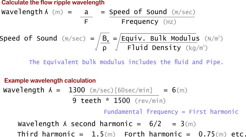
3. The flow ripple gets reflected back by the components at the ends of each pipe. These reflected ripples create standing waves that can have a higher amplitude than the original source wave. The wavelength of a flow ripple for the first harmonic of a pump can be calculated as shown in our sample calculation diagram.
How to reduce noise transmission
We have two key tools for reducing the transmission of fluid-borne noise. We can prevent the generation of standing waves or modify the circuit impedance to limit the pressure ripple created by the pump's discontinuous flow.
The first section of pipework between the pump and the first component in the circuit will be the most important. This section sees the full amplitude flow ripple and then sends the attenuated wave into the rest of the circuit.
Preventing standing waves
A standing wave will only be generated if the initial pipe length between the pump and the first component is greater than the harmonic frequencies generated by the pump. From the calculation above we can see this would be 9m for a typical 9 tooth gear pump rotating at 1500rev/min although we should also consider the higher harmonics which may also be significant.
Changing the length of pipework or adding more flexible hose has the potential to reduce standing waves.
Reducing the circuit impedance
There are several practical ways we can reduce the impedance of a circuit although these will probably rely on experimental changes based on expected results, rather than theoretical proof by calculation. Things that have been often shown to help by practice and calculation include:
Using flexible hose instead of rigid pipes. Flexible hose has a lower impedance than rigid pipe so generally reduces the pressure ripple.
Stub tubes running off the main circuit work should also reduce the pressure ripple. These work in a similar way as running two pipes of different lengths in parallel.
Hydraulic silencers can work well if they have been designed to match a particular noise source frequency. These operate in a similar way to car silencers.
Accumulators may also help by changing the circuit impedance but probably only at the fundamental frequency rather than all harmonics.
Hydraulic filters should reduce the pressure ripple if they are located close to the pump. It's typical for these to be one of the first components in the circuit and good practice to have the pump, a short length of flexible hose, and then the pressure filter. Perhaps with a safety relief valve set off to one side in a stub tube.
All valves and filters etc. will have some effect on the circuit's impedance although it's difficult to predict what if any effect it will have on the pressure ripples created. As we mentioned earlier, the first section of the circuit is key because the flow and pressure ripples will be larger there and then attenuate further as they migrate through the circuit.
Reducing valve instabilities
Hydraulic systems must always be free from air in the fluid. If it's safe to do so, you can bleed the air from the highest point in the circuit or raise the pressure to over 70 bar, which should force the air into solution and take it away with the circulating fluid. Check where the air may be entering the system e.g. damaged seals, fittings or pilot vent holes. Replace worn valves or try using pilot-operated or spool valves instead of direct-acting or poppet valves. If the system operates in closed loop or you think it has something to do with long pipe lengths then you need to consider the full system dynamics, probably discussing this with an experienced controls engineer.
Reducing cavitation/aeration
Increasing the size of the valve causing the cavitation should reduce the high local restrictions and flow rates that lead to cavitation/aeration. If changes to conditions that cause cavitation are not possible then using a sacrificial plate for the flow to impact against can create conditions where the collapsing bubbles make less impact, although they might slowly chip away at the metal surface causing additional contamination problems.
How noise is radiated from hydraulic equipment
The pressure ripples that have been transmitted all around the circuit by the pump's flow ripple or valve movements, may have enough energy to excite any/every component, causing either the casings to deflect or the components to move on their mountings, either of which will translate into air-borne noise.
Sometimes the installed power is so high that air-borne noise becomes a general issue with many parts of the circuit vibrating. Any pressure ripple that transmits enough energy can excite the pipework or components enough to generate air-borne noise. The air-borne noise might come via the flexing of the pipe walls or distortions in the component bodies. Air-borne noise can also be generated by the movement of the pipework or components on their mountings.
In other cases it may be just one or two factors that are creating unacceptable levels of air-borne noise. These might be caused by:
Standing waves can generate large pressure ripples at one position within the circuit. These typically place much more energy within one pipe or component so this will be the area that vibrates or flexes the most and therefore generates the most air-borne noise.
Every component will have at least one fundamental oscillating frequency and often include several harmonic oscillating frequencies based around this. If the frequency of the pressure ripple matches the fundamental frequency of the pipework or components then the equipment is likely to start oscillating more violently, creating additional air-borne noise. Audible noises often arise when a particular frequency in one section of the circuit coincides with the natural frequency of a component at that particular point in the circuit.
How to measure air-borne noise
The major problem with fluid-borne noise, circuit impedance, and pressure ripple, is that they are virtually impossible to measure at all of the different locations around the circuit. By comparison, air-borne noise is relatively easy to measure using a simple dBA sound meter. Analysing the result is, however, not straightforward or definitive but with care, it is often possible to use this information to narrow down the sources of the noise and the components that are radiating the noise.
How to reduce air-borne noise radiation
We have already discussed techniques for reducing the original sources and transmission of noise signals so we won't repeat them here, but remember, it is always better to remove the cause of the noise rather than trying to reduce its final effect.
Use the frequency data from the air-borne noise test to identify which noise source is the original generator. It should be possible to look at each of the high amplitude frequencies and relate these back to identify what is causing the noise. This might be the pumping element's fundamental or higher harmonic frequencies, higher frequency valve oscillations or even higher frequency cavitation noise.
If you can't remove or reposition standing waves then the air-borne noise causing vibrations can be reduced by improving the component or pipe mountings where the standing waves occur.
Changing the isolation mount type, number, or position has the potential to significantly reduce the air-borne noise generation. It may also change the natural oscillating frequency of any pipes or components, therefore reducing the air-borne noise they emit.
As a last resort, enclosing the equipment within a soundproof casing is an effective way of ensuring that operators are protected from noise. These topics are widely covered on different websites so we will not cover them again here.