Understand where and why directional valves are used. The different types available and how they work.
Self-study lesson plans and training record download page.
1-2 What directional valves do and where they are used
Directional valves control the direction that fluid flows. They start and stop the flow, or direct it along different pipelines. Directional valves are used to control the movement of hydraulic actuators, primarily cylinders or motors. This may be a single, hydraulic on/off switch to start and stop a hydraulic motor, or a 4-way, 3 position valve that stops, extends, and retracts a cylinder.
4-way, 3 position valves are a common format that has four ports e.g. a supply and tank return line plus A and B system ports. The valve can switch the flow between the supply port and the A port in one position, or the B port in the second position. It will also have an unactivated, rest position, which will shut of the supply to either port. The A and B ports typically connect to the bore and annulus ports of a cylinder to extend and retract a cylinder.
Directional valves come in many different switching configurations. These are arranged to control all types of hydraulic switching logic.
Virtually every actuator that does not have a proportional valve, will have a directional valve to control its movement (NOT its speed).
1-2 How directional valves work
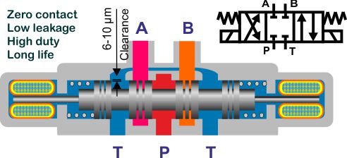
Directional valves predominantly contain a single sliding spool that moves up and down inside the valve to direct the hydraulic flow along different pipelines. The spools and bores are made to very high tolerances and require specialist machines and skills to maintain the high-quality bore and spool concentricity and straightness, throughout their length.
Look at the different directional valve symbols to see which ports they switch from, to or between.
Valves are typically two-way (P to A), three-way (P to A then P to B) or (P to A then A to T) or four-way (P, T, A, B connections). 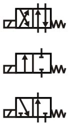
Valves can also have either two or three positions and are switched between the different positions by either, hand, electrical solenoid, air or hydraulic pilot.
Some valves have springs to return them to their fall-back condition, some have detents that hold them in position until they are reset.
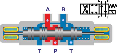
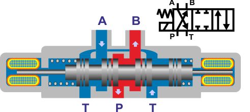
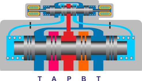
The following images show a typical 4-way, 3 position valve in different operating positions and with different centre overlap conditions.
P to A, B to T connection
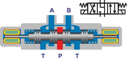
P to B, A to T connection
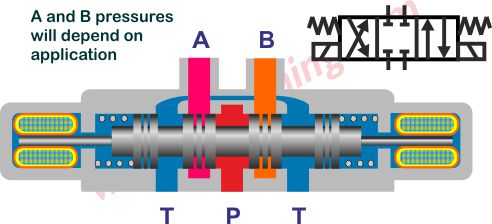
A and B to tank in center
Closed center
Condition while switching
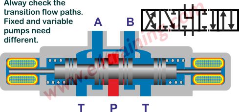
The condition between switching can also be important. A fixed displacement pump will need at least one port to remain open while switching or there will be nowhere for the flow to go and pressure will spike too high. However, a pressure compensated pump will require the supply port to stay isolated from the tank line while switching or the pressure will drop.
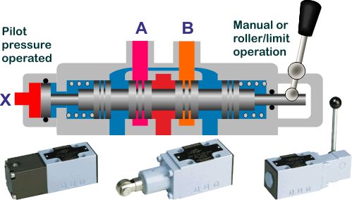
Pilot operated for large flows
The force required to switch the larger directional valve spools is generally higher than can be achieved by electrical solenoids, so often we will see a smaller hydraulic pilot valve fitted on top of the main spool section. This smaller valve will supply hydraulic power via the internal pilots, to the end of the main valve's spool, therefore switching the valve at a controlled speed.
2-3 Different types of valve
Directional valves are also be known as on/off, black and white, or 3-way etc valve.
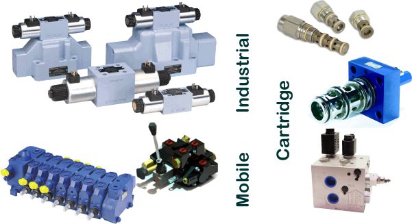
There are three main types of directional valves:
- Cartridge directional valves that fit into custom manifolds. Industrial CETOP, plate-mounted directional valves.Mobile, mono-block slice directional valves.
All come in a range of sizes and flow capacities.
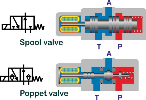
We have not included poppet-style directional valves in this list as these are a significantly different group of valves and will be covered in a separate training module.
Directional valves are either open or closed, there is no in-between, part flow position.
Don't confuse directional valves with proportional valves. Proportional valves provide a measure of flow control depending on how far the spool is moved. Their operation and performance are markedly different.
As with all hydraulic valves, the only way to confidently identify a valve is to make a note of its full part number and look the number up in the manufacturer's datasheet. There can be a vast number of different design options including:
Spool configuration and crossover conditions e.g. as it passes from one condition to the other are the ports linked open or linked shut.
Solenoid types, voltage, connector style, power-save options.
Material types, seals, body, paint, label.
One or two-stage valves. Multi-stage valves have the option for different connections between the two valves or bringing in remote feeds and bleeds.
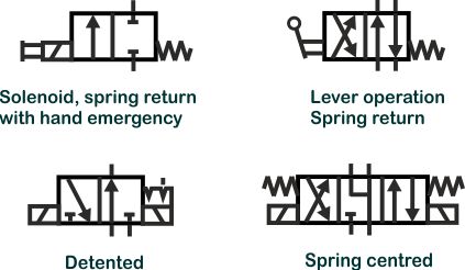
Hand, ball or air operated
Activation and detent symbols
Advanced directional control valve training
Learn more about directional control valves in our 'Professional Training Section'. Understand their design features, performance limits, and how to specify directional valves.