Self-study lesson plans and training record download page.
Scissor lift design project tutorial
Start by taking this 'scissor lift circuit design' tutorial
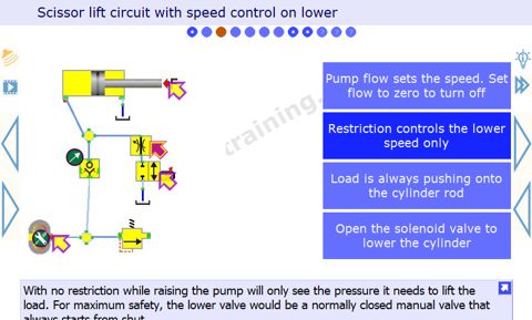
Circuit 1 - Basic, gravity fall, scissor lift circuit
This is the most simple scissor lift circuit possible.
In the standby condition shown the cylinder will fall under its own weight, with the flow being released through the open solenoid valve. The pump may still be running but has no pressure on it because the flow goes straight through the check valve and 2 way 2 position solenoid valve.
When the solenoid valve is switched to shut, no fluid can escape so the cylinder will start to extend. The pressure in the fluid will be equivalent to the load on the cylinder e.g. more weight, more pressure.
At the end of the cylinder stroke, the fluid has nowhere else to go but across the relief valve. The pump pressure will immediately increase to the relief valve operating pressure. All of the pump energy will be converted to heat and the reservoir might overheat after only a few seconds under these conditions.
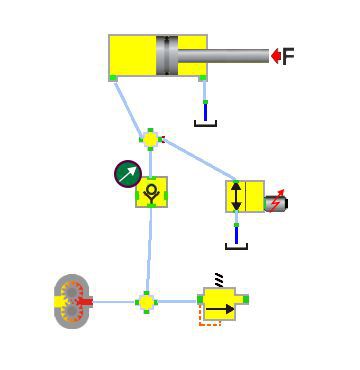
Circuit 2 - Dubious flow control circuit
This circuit includes a flow control valve in the cylinder supply line. This could be used to control the raising and lowering speeds. However, there are several potential issues with this.
Operate circuit 2 here to find out what the problems might be.
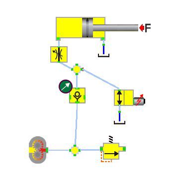
Circuit 3 - Flow control while lowering
This circuit has the flow control in the lowering line. Not the raise line. This means it can be safely used to control the lowering speed and leave the pump to control the raise speed without any big power loss.
Operate circuit 3 here and work out what one of the problems might be.
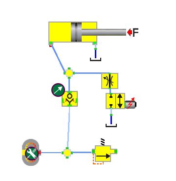
Circuit 4 - Double cylinder lifting
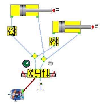
This circuit has two cylinders that must work and move together. To do this they must be mechanically linked or the cylinder with the lowest load will just move on its own. There is no flow control while raising so the speed will be set by the pump flow.
It is a legal requirement for hydraulic lifting systems to have a restriction that will prevent uncontrolled lowering speeds. The bore line flow control valves will provide this however, we are now using a four-way three-position valve so the pump will be driving the cylinders down, rather than leaving this to gravity.
Operate circuit 4 here and experiment with different cylinder loads and flow control setting. The simulation does not have a mechanical link between the cylinders.
Circuit 5 - Load holding PO check valve
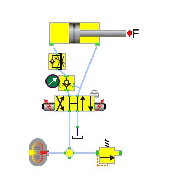
This circuit includes a pilot operated check valve to hold the load stationary at any position. Flow travels through the check valve when raising and the pilot feed from the lowering line opens the check valve while the cylinder is being driven down.
Operate circuit 5 here and experiment with the flow control setting and pump flows while lowering.
Circuit 6 - Hose burst safety valve
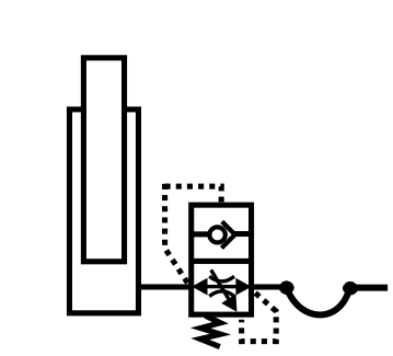
Hydraulic hoses have a limited life and therefore the potential to fail. In many lifting applications it is, therefore, a legal requirement to include some form of hose burst protection valve. In the example shown the raise and lower operation works fine while the hose is intact. However, should the hose fail and the cylinder start to fall quickly, the pressure drop across the valve will cause it to switch and the check valve will stop any further movement.
Circuit 7 - Shock relief valve
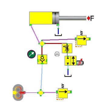
Finally, there is one addition we should consider for several of the designs. This circuit includes a relief valve directly connected to the cylinder bore. This is not required to compensate for thermal expansion of the fluid as the system should never be left extended. However, it may be required to protect against shock loads on the cylinder rod because the system relief valve is separated by a one-way valve.
Potential circuit design problems
These are the answers to some of the problems posed above.
In circuit 2 we can only adjust raise and lower speed together. But they will not be the same as the loads are different and therefore the pressure drop across the orifice will be different when raising and lowering. Which means the flow will to. Also, if you restrict the pump supply flow then it will just create more pressure and heat. Eventually, the relief valve will open and the reservoir will probably overheat.
It’s a well-known fact that if an operator can do something stupid, they will. So someone is bound to adjust the flow control valve to a level that will compromise the circuit operation.
In circuit 3 we will definitely need to switch the pump off once the cylinder is fully extended as the pump flow across the orifice will generate heat and probably damage the fluid and pump.
circuit 4 should indicate how difficult it is to raise two cylinders at the same speed when loads keep changing. Mechanical synchronisation is the easiest but there are other hydraulic options if this is not possible.
circuit 5 big inefficiencies can occur when driving down cylinders with a flow control valve and fixed displacement pump.