Self-study lesson plans and training record download page.
Terminology Relevant to Instrumentation
Working Range:
The range values the sensor is designed to measure i.e. the datasheet performance specification is valid.
Operating Limits:
The limits to which the sensor can experience intermittently without risk of damage.
Sampling rate:
The sampling rate is the number of samples taken per second. If your sampling rate is only 0.25 seconds then you are likely to miss a pressure peak that only lasts 0.01 of a second.
Hysteresis:
Hysteresis is the difference between measurements as the value rises compared to when the value falls.
Accuracy:
Accuracy defines the amount of uncertainty in a measurement. This may be due to offset errors or gain errors and is quoted as part of the signal being measured.
Precision:
Precision defines the measurement reproducibility e.g. if repeated signal measurements at the same value are close together then the instruments show a high level of precision.
Resolution:
Resolution is the ratio of the largest and smallest signals that can be measured. For example, an instrument may have a 10V range but working through an A/D converter will have a minimum increment that can be detected.
Sensitivity:
Sensitivity is the smallest quantity of change that can be detected.
Caveats and Qualifications
Carefully check the performance data for the instrumentation you are using. This module discusses general performance data, for example purposes only. There are a wide range of different instruments on the market so our examples may be significantly different to the products you use.
Transducers, transmitters or sensors
Different industries have different understandings of the meaning or importance of these terms. For some it's whether they are voltage or current devices and other it's how they are used. This module simply uses sensor to describe a device that reads something and transducer for one that reads and outputs the data with a display.
Common issues or points to be aware of
Because modern transducers provide clear digital displays, which unfortunately people always assume are correct. A 600 bar pressure transducer with a 1% tolerance, for example, may display 6 bar while there is only 1 bar pressure acting on it. It's easy to confuse which transducer is being used and think that 600 bar transducer can read under 50 bar accurately, which it's not doing.
Modern transducers need a data logger and analyser, or compatible meter to read their results. These often have scales or factoring to convert the reading into an output and these must also be calibrated along with the sensor. An important factor in the calibration can be software updates. It's common for new meters or analysis equipment to be delivered with older software than is available online. Always check and download the latest software fory our device and check the calibration of your sensors and display meter work together.
It's likely that sensors from one manufacturer will only work with their own data logger so chose your initial supplier carefully.
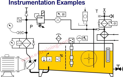
Hydraulic Pressure Measurement
There are two main techniques for measuring hydraulic pressure. An analogue, manometer style pressure gauge or an electronic pressure sensor. Both have different benefits and limitations and if possible it is a good idea to include both within your system.
Analogue, manometer pressure gauges provide a quick, simple and reliable way to check the working pressure. They employ a curved bourdon tube that deflects under pressure to move a needle around a clearly marked scale.
Benefits:
Simple to read and understand, clearly display when exceeding normal range even if out of calibration, damps out dynamic oscillations when the mean pressure is required.
Limitations:
Difficult to read an accurate value, no record of results, damps out dynamic pressure spikes so maximum values can be missed. Loose calibration if over-pressurised.
Pressure transducers offer a very accurate and versatile way to record system pressure. There are a number of different design technologies each with different ranges, accuracies and reliabilities. It's likely that different industries will utilise the sensors most suited to their machines.
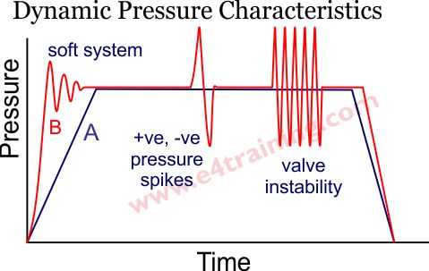
Pressure transducers generally have good dynamic performance and can highlight dangerous pressure spikes or high-pressure rise rates. Both of which can lead to early pump or component failures.
Benefits:
Accurate electronic readings that can be saved or stored as required. Measure dynamic changes not shown with manometers. Clear digital readouts.
Limitations:
No obvious evidence of the level of accuracy, particularly at low readings.
Difficult to read average values if the signal is highly dynamic.
Contamination Particle Counters
Modern contamination meters use either infra-red or lasers to count the number and size of particles in the fluid. The latest, lower cost design can be installed alongside existing pipework to continuously provide the actual, instantaneous, contamination levels. They require a consistent flow rate through the meter to provide a reliable reading and location may also be important as it's quite possible that different parts of the hydraulic circuits see different levels of contamination.
An example of their effectiveness is that if you use them in production line test rig they can provide an instant printout or recording of the actual contamination level and when the pipes are disconnected to install the next test valve, the meter will detect and display the additional dirt that has entered the system from the open pipes, even if quick release couplings are used.
The choice between manufacturer type, laser or infra-red may be based on the accuracy, robustness, cost, type of fluids that are compatible with the meter or its ability to differentiate between air bubble, water droplets and solid contaminants.
Benefits:
Help to resolve hydraulics' biggest problem in a low cost, reliable way. Can help you discover valuable information about your system such as where and when contaminants get into the system and how effective the filtration system is at removing them. We highly recommend everyone buys one.
Limitations:
Sensitive to flow rate and location. Some will record water or air bubbles as dirt. Different meters required for different fluids.
Hydraulic Flow Meters
Hydraulic flow meters are available in a range of different design types. The most commonly used are turbine flow meters and external gear motors. In general, the turbine meters provide a low cost, relatively robust solution against the higher accuracy and price for the gear motors.
Benefits:
Much safer and cleaner than the old 'measuring the volume of fluid going into a bucket' technique. Can be used to identify issues that simply measuring the cylinder timing cannot.
Limitations:
Turbine meters are not accurate towards the bottom of their range but still provide accurate looking digital readouts.
High pressure rated flow meters can be expensive so often low-pressure versions are installed to measure the flow in the tank return line.
Flow meters are not the most robust items so expect recalibration and replacement costs.
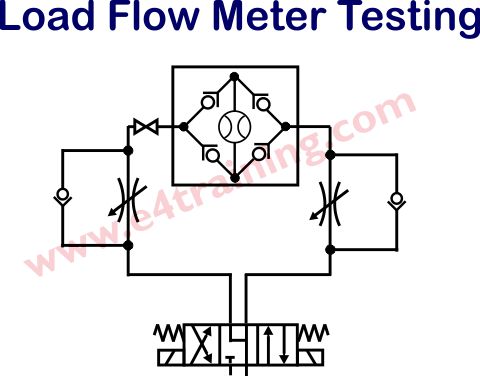
The diagram shows a flow meter in a Wheatstone bridge circuit, complete with a loading valve. This arrangement could potentially be used to set up the flow control valves before the load is available, or as a replacement during commissioning.
Fluid Level Gauges
Fluid level switches can be one of the most troublesome and unreliable parts in your system.
There are many different design types available but all have to overcome the difficulty of measuring fluid that can move in continuous waves or splashes around the tank and still remain reliable in the difficult environment of both air and water. These challenging conditions require both a robust switch an intelligent software to differentiate between a moving vehicle, and splashes, from instant level changes.
Level Switch Options:
Traditionally float switches have been used, particularly on static, industrial applications. However, these do have moving parts so are more prone to reliability issues. Capacitance change or light change switches are more robust and much smaller although they do require a penetration in the side of the reservoir for each one, which is an extra leak risk.
Analogue and Continuous Digital Readout Options:
To obtain a continuous readout of the fluid level you will need a more complicated transducer. This may variable capacitance or resistance, multiple switches, pressure differential and radio wave. All will exhibit different levels of robustness, reliability, accuracy, consistency and suitability for different fluids or environments. They will also need some specialist software or electronics to make sense of the output signals.
We recommend as robust a solution as possible, especially for mobile environments.
Temperature Measurement
Temperature measurement is not generally an issue because the accuracy of most instrumentation is easily sufficient for general needs. Many pressure sensors already have temperature measurement built in.
Accurate temperature control will probably be critical for the performance and reliability of your system e.g. keeping the operating limits between 40 to 50C for example. If your application does not have its temperature limits specified, or you are unable to stay within these limits, then you should check the performance of the system across the temperature range and take the appropriate actions. For example, it is unlikely your pump will work well at very low, or very high pressure and will probably have a much-reduced service life. Consider a warm-up routine or breaks if the fluid gets too warm.
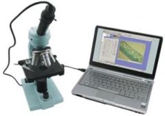
Microscopic Analysis
One of the most effective ways of reducing the contamination levels in your circuit is to send a sample of fluid away to a laboratory for particle analysis e.g. to find out what materials are present and therefore, where the dirt is likely to have come from.
Although very effective the laboratory analysis will be time-consuming and expensive. It is sometimes expedient to find a quick alternative and I've always found that even having a low cost microscope with an inbuilt digital camera on my desk worked very well. They are inexpensive to buy, the quality is sufficient to diagnose many material sources and you get a digital photograph for management reporting and your records. Provided you can control some sort of consistency in your sample collection, this will also make a useful preventative test during the assembly process. For example, wipe around the inside (360 degrees on one or a number of bores) of a new manifold or component with a clean, lint-free cloth and you will get an appreciation for how the clean the manufacturer's washing process has or has not been. This can save a lot of time with faults during final test and commissioning.
Data Loggers, Acquisition and Analysis
More information to follow soon.
Further Reading
There are some nice videos and resources on the Webtec website.