Self-study lesson plans and training record download page.
Hydraulic Valve and Cylinder System Design Overview
This module explains the calculations behind our hydraulic valve and cylinder system design guide. It clarifies the parameters you need to enter into the software and explains the basis and significance of the results.
While this simulation does provide some intelligence and sizing routines it can never predict every system that might be designed. Users must enter the data appropriate to their own equipment and think about the validity of the results shown. It's likely that if you cannot replicate your hydraulic system design within this software, then your machine will not work. However, if you do get realistic numbers from this simulation then that will not ensure the machine will always work. Our design guides are only intended to help initial scoping and understanding, always use written calculations for final checking and approval.
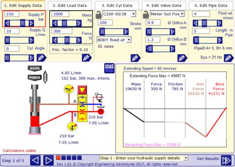
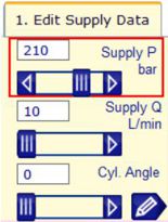
Enter The Supply Data
First make sure that the lock symbols in the product selection groups are unlocked, or click on them to unlock. With the cylinder size fixed, for example, you will not be able to change the available force.
Enter the available supply pressure and flow. You may need to adjust these later depending on whether you have pressure compensated or fixed displacement system.
The supply pressure has a direct relationship on controlling the load. If the force balance graph does not finish on the middle line then the cylinder will not move in the direction required. You should also have extra pressure available to control the flow, probably a minimum of 30% or 30bar, although this will differ for each application.
The cylinder speed is generally controlled by the valve restrictions, rather than the supply flow. Too high a supply flow will just mean the excess flows across the relief valve or pump compensator unless you have a fixed displacement system.
Adjust the cylinder angle to match your equipment. Or experiment with the different angles the cylinder may see in service.
Select the edit button (pencil) to open the detail supply data panel. This show the maximum cylinder force and speed that is possible with the supply conditions. These are not the actual values but should provide useful design information. Use the edit box to record additional information about the supply system, all information will be useful to the supplier to advise on duty and maintenance procedures etc.
Enter Load Data
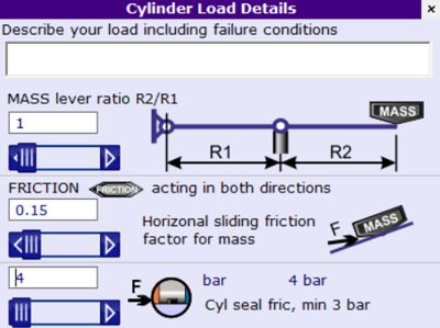
The load is made up of two key components, the mass and the force acting on the cylinder.
If a cylinder is simply lifting a weight vertically into the air then only a mass is required. This will be multiplied by gravity to give the force. If the cylinder is horizontal then the mass still the same but gravity has no effect on force apart from setting the frictional load.
The force acts independently of mass. This may be pressure from another cylinder or clamp for example.
In the load detail panel, you can change the lever ratio for the mass. This is important for calculating the system natural frequency and therefore the speed at which it can operate, without oscillating. If you are uncertain about the exact nature of your load then try hitting it with a big hammer and measuring the frequency of oscillation in the pressure signal. That frequency should tie in with the frequency calculated in this application, when you've got your values correct.
Load friction can be set between 0 to 1. This only applies fully against a horizontal cylinder or fractions thereof until the cylinder is vertical.
All cylinders will have some seal friction. This is typically set to 3 or 4 bar but depends on the cylinder seals used.
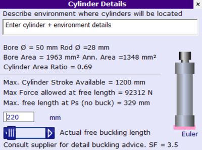
Enter the Cylinder Data
When the cylinder data is unlocked the program may automatically select a cylinder size based on your load or speed conditions. It's useful to lock this to one cylinder once you believe you have the most appropriate size, otherwise, test results can get confusing.
Select the correct cylinder by making sure you have enough force to drive the load in both directions while making sure there is still enough pressure drop to control the speed of movement. Use the force balance graph to visualise the how close the available force is to the required force. Apply your own safety factor based on how much you believe this could vary in service or how accurately you need the movement controlled.
Sometimes the limit for sizing a cylinder is the rod buckling limit. This depends on the cylinder stroke and mounting style. Enter the stroke underneath the cylinder type then select the mounting style from the drop-down list. A graphic representation of the mounting points is shown around the cylinder animation.
Open the cylinder detail window to see a calculation of the maximum force and dimension limits. Use this information to experiment with different cylinder sizes until you achieve a design that remains within acceptable buckling limits. The calculations used are generic and should apply to most cylinders, however, you should always check with the manufacturer datasheets for specific advice.
Enter Valve Data
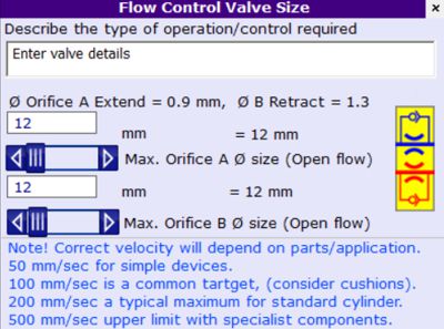
Select the type of control you require from the drop-down list. You can, of course, experiment with the different options to determine which one is appropriate based on the results from this simulation the approach is more likely to come from the control requirements of the overall machine design.
The program requires the user to enter both ingoing an outgoing orifice sizes. These are actually set in the same way the valves would be set on the system e.g. adjusted until the correct flow rate and cylinder speed are achieved. The actual size is not that important although it is interesting to compare to the nominal size of valve selected, using the manufacturer's performance data.
Opening the valve detail data window shows a second orifice size which represents the reverse flow conditions for the meter in or meter out control. This will typically be the nominal size of the valve but check with the manufacturer datasheets to confirm the actual size or pressure drop.
Enter Pipework Data
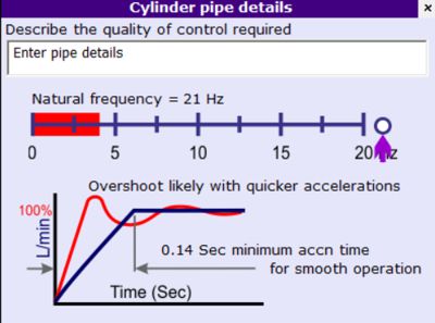
Enter the maximum fluid velocity permitted in the cylinder lines along with the length of pipework between the valve and the cylinder. The program will then calculate the system natural frequency and minimum acceleration time for smooth operation. Simple designs often tend to lie around 10Hz, which is normally quite acceptable. You should avoid designing systems under 4 Hz as these are likely to oscillate when moved. If you require a higher performance then you may need to build a stiffer system to achieve the minimum acceleration times required; the system controls engineer should be able to advise on the necessary target value.
Export the Result to a Spreadsheet
Once you have decided on the most appropriate design you can export the results to Excel or any other spreadsheet. Use the 'Get Results' to go to the results page. On the registered version you can copy or email the data to your PC. With the unregistered version, the data will be emailed to yourself and a potential supplier in your area.
Next Open Excel. Paste your comma-separated values into the document, column 1.
Select column 1 and open the 'DATA' tab.
Click on the 'Text to Columns' button and follow the wizard (delimited-comma).
You will then have an excel table you can manipulate as required.
Make sure you check the results with your own calculations in Excel or Mathcad etc.